Building a Jupiter Ace
Last updated: Mar 14, 2020
I have been tinkering with electronics since I was a kid, and since my high school years I dreamt of building a computer from scratch. Back then, my dream CPU was the venerable Motorola MC6809 and I spent my lunch break drawing schematics and pondering what chips I would want to use. That design work stayed theoretical, but recently I came close to this dream when I started to build a Jupiter Ace home computer from parts.
The Jupiter Ace was a home computer similar to the Sinclair ZX series, and in fact it was designed by some engineers that previously worked for Sinclair research. It thus does not come as a surprise that the Jupiter Ace was similar to the Sinclair systems in several respects: It used a Zilog Z80 CPU and it had a rubber keyboard not unlike the ZX Spectrum. The most important difference, though, was that the Jupiter Ace had FORTH as its programming language. It was quite a bold decision to not go with BASIC like virtually all other home computers of the time did, and it is probably fair to say that FORTH was one of the reasons why the Jupiter Ace flopped commercially.
Another difference between the Jupiter Ace and most other home computers of the time was that it was built entirely out of standard chips. Because no special parts are required, several people have built clones of the Jupiter Ace over time. I had pondered doing that myself for quite a while, and when I found that the original manual for the machine had been republished, I went ahead and sourced the components.
Building the Machine
Even though the Jupiter Ace is not a very complicated system, it still consists of 25 Chips. I decided that rather than designing a PCB and having that manufactured in China, I would use Veroboard and a wiring pencil. I used that technique for many years, but this was by far the largest project I ever undertook.
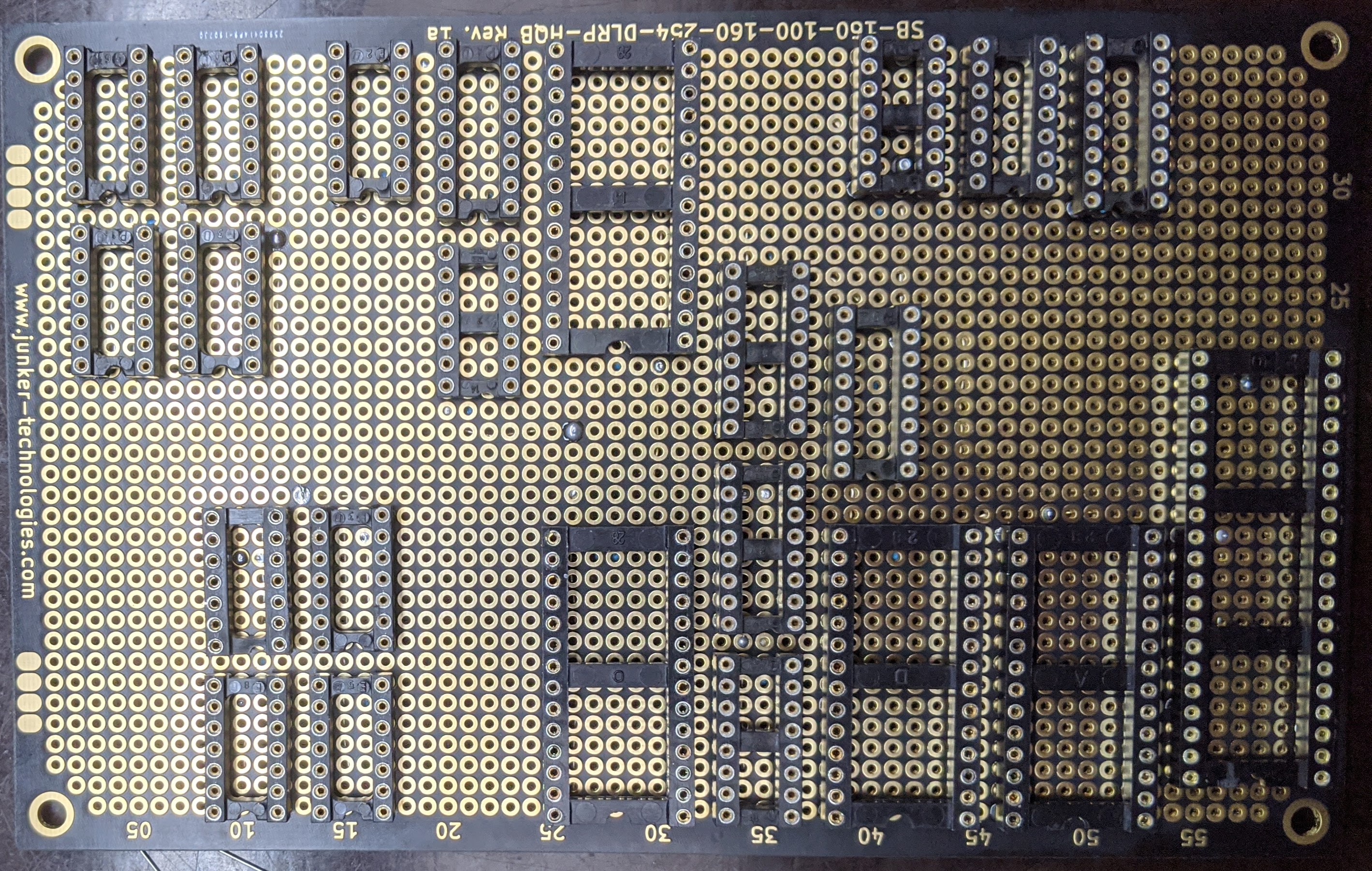
I bought a high quality 100x160 mm Veroboard and placed the sockets for the chips matching the layout that someone else had used when building an Ace from scratch.
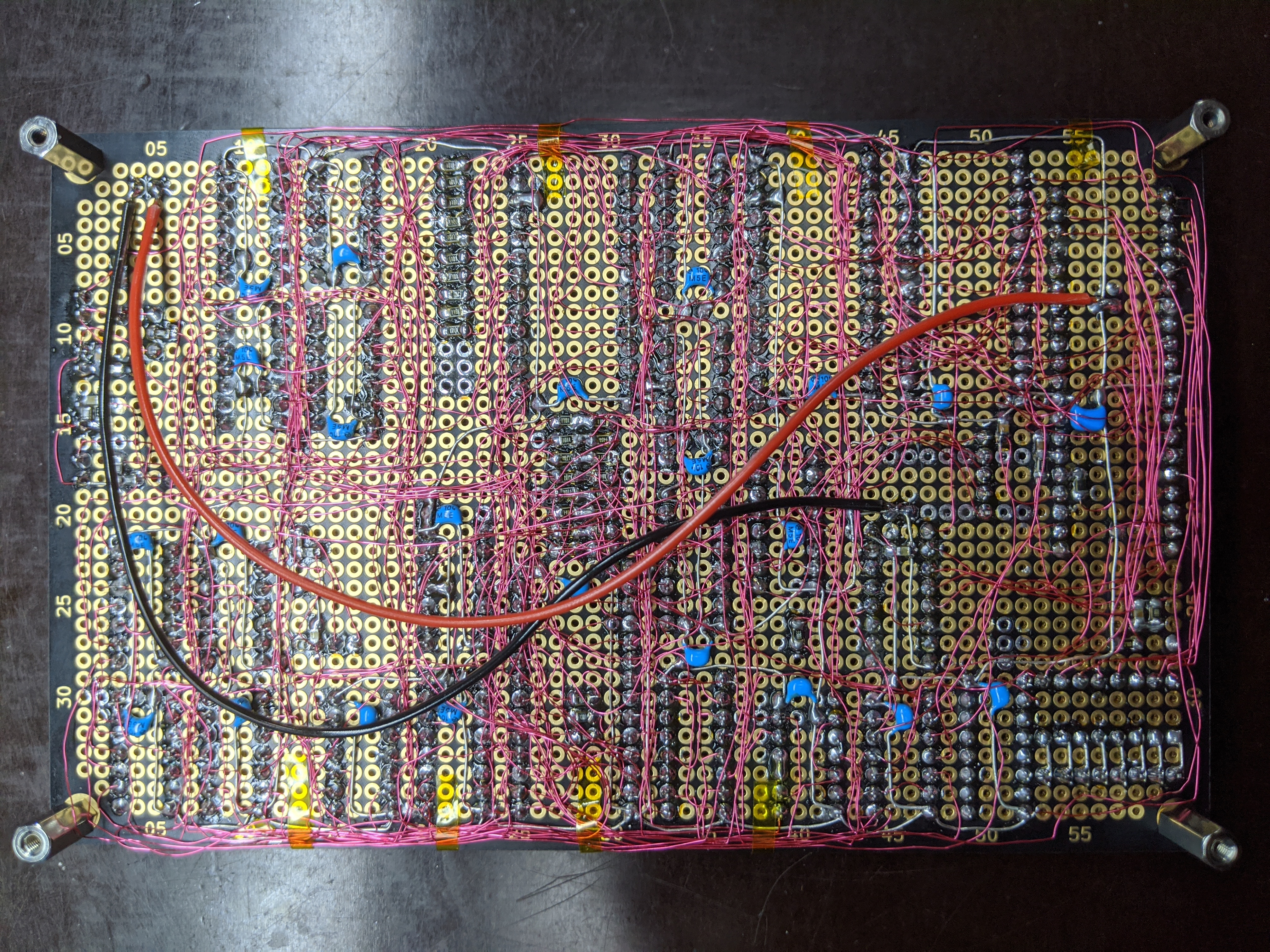
In order to orient myself on the backside of the board so that I find the pins that I needed to wire, I needed a map. I took a photo of the solder side, placed labels on the photo using an image editor and printed that out on A4 paper. I labeled the chips numbers as well as pin numbers, but I still made several mistakes when wiring. The map was a huge help, though.

Using wire, I connected the power supply and ground pins of all chips and placed decoupling capacitors near the supply pins of all chips. Then, using the schematics, I wired all the connections with Verowire.
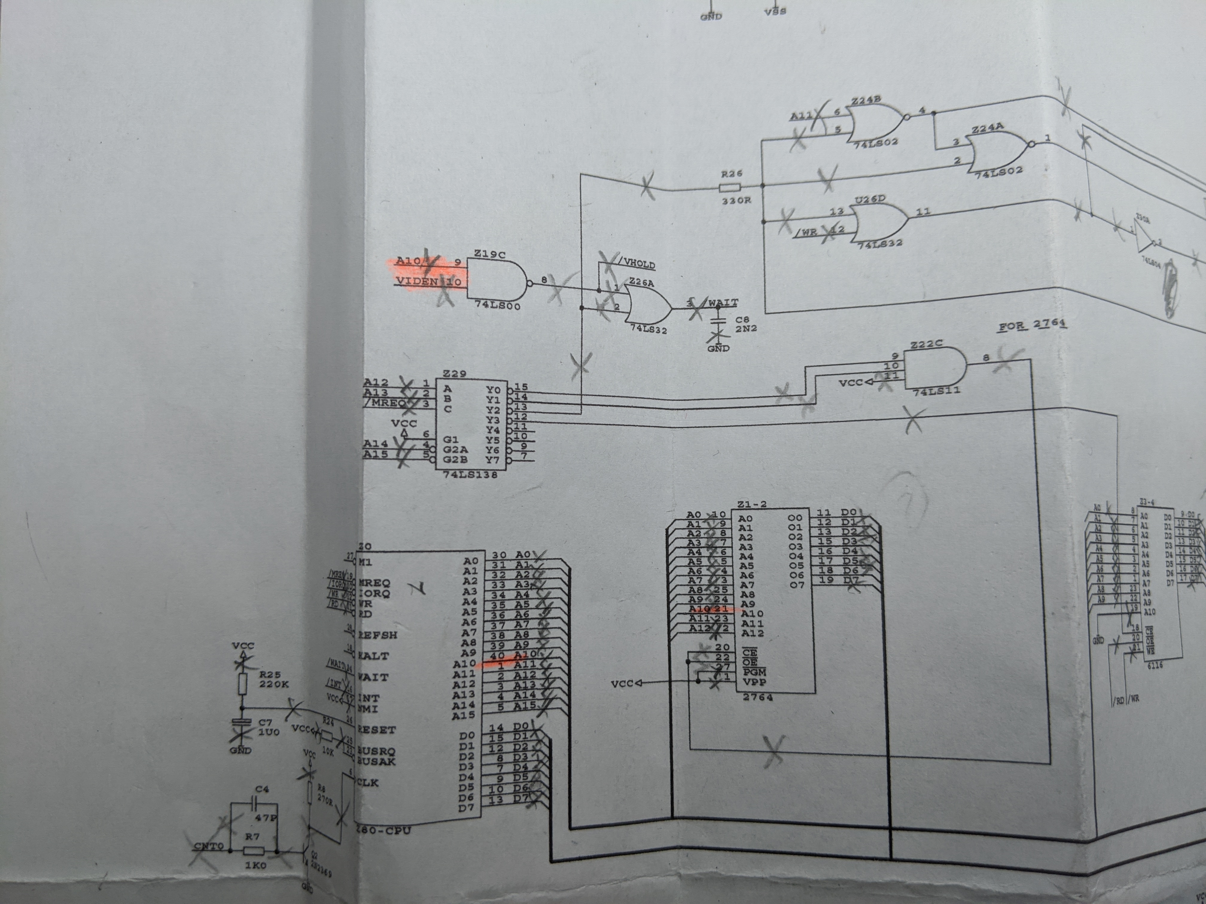
Using a hardcopy of the schematics in A3 format, I tracked my work by crossing off each connection after I soldered it.
Bringing it up
Verify connections
Using the schematics, I checked every connection for continuity. For each chip on the board, I verified that it had the required connections. Doing this, I found numerous mistakes that I had made when wiring, so I’m glad having gone through this.
Check supply rails
I checked the supply rails to ensure that there was no short between +5V and ground. I then connected the power supply to the unpopulated board and verified that the correct power supply pins of all chips showed the correct voltage.
Check clock generation
I populated the chips needed to generate the CPU clock and the various derived clock signals for the video generation circuitry.

I then verified that the CPU received the correct clock signal and that the clock divider supplied appropriate frequencies on the output pins. As I could not find a 6.5 Mhz crystal, I used one with 6.5536 Mhz, hoping that the resulting video signal would be close enough for my monitor to synchronize with. I measured the pixel and frame frequencies, which expectedly were a bit higher than nominal.
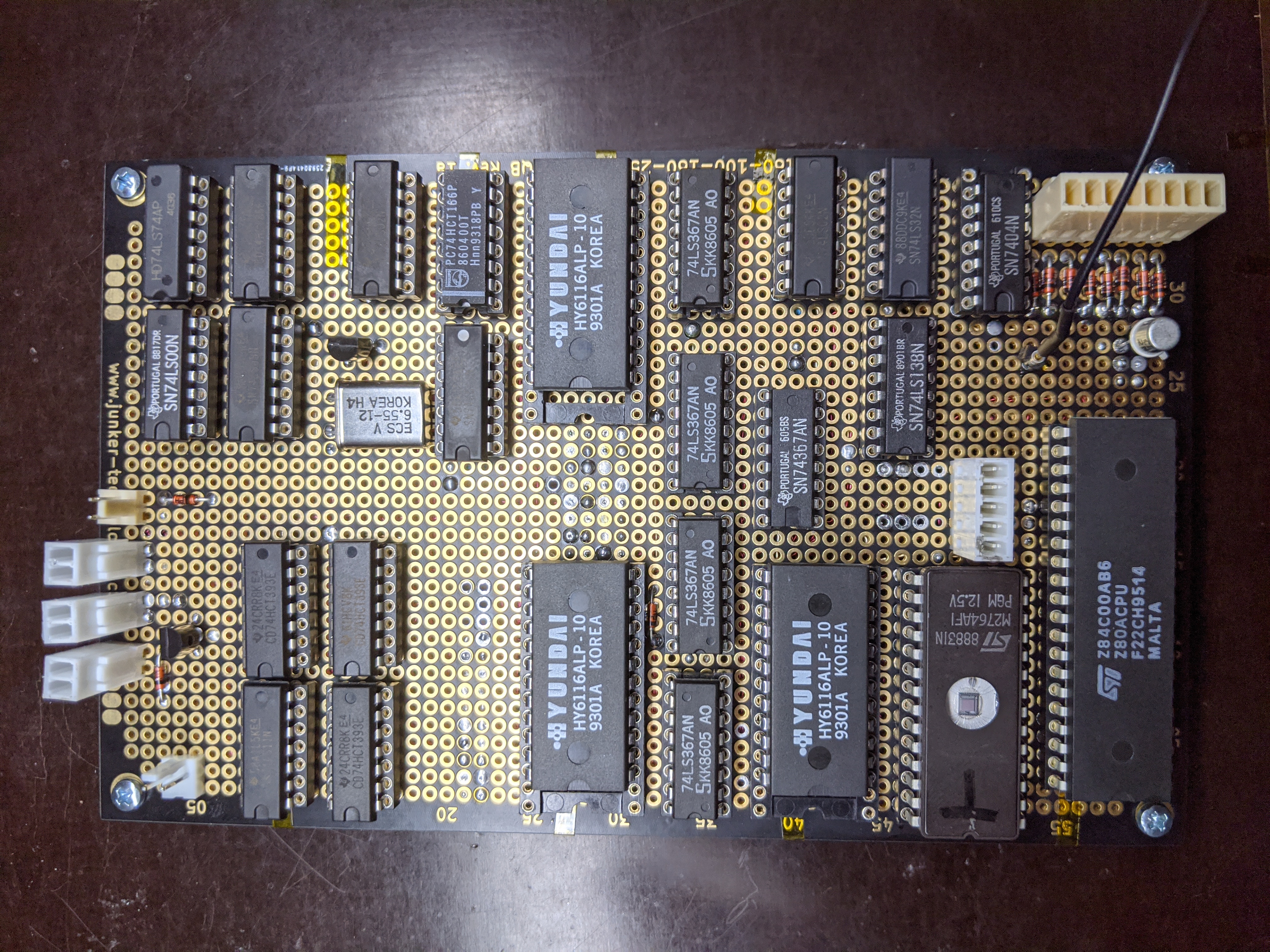
Put on the Chips
At this point, I felt sufficiently confident that I could put on the rest of the chips.
Troubleshooting
With all the chips populated and the Jupiter Ace ROM image burnt into the EPROM, I connected the machine to a monitor and started it. Not surprisingly, I did not get a stable picture, but I could see what seemed to be the 4 by 8 pixel cursor running over the screen. The output signal sent to the monitor seems to somewhat resemble other video signals that I have seen, but apparently something in there is not to the liking of all of my monitors so that they don’t synchronize.

I will have to investigate how this signal is wrong and what I can do to fix it. The basic waveform does look like a proper composite video signal with line and frame synchronization pulses and also what appears to be the cursor, seen as small needles near the end of each frame.
I also wanted to confirm whether the CPU itself was running, so I hooked up my logic analyser.
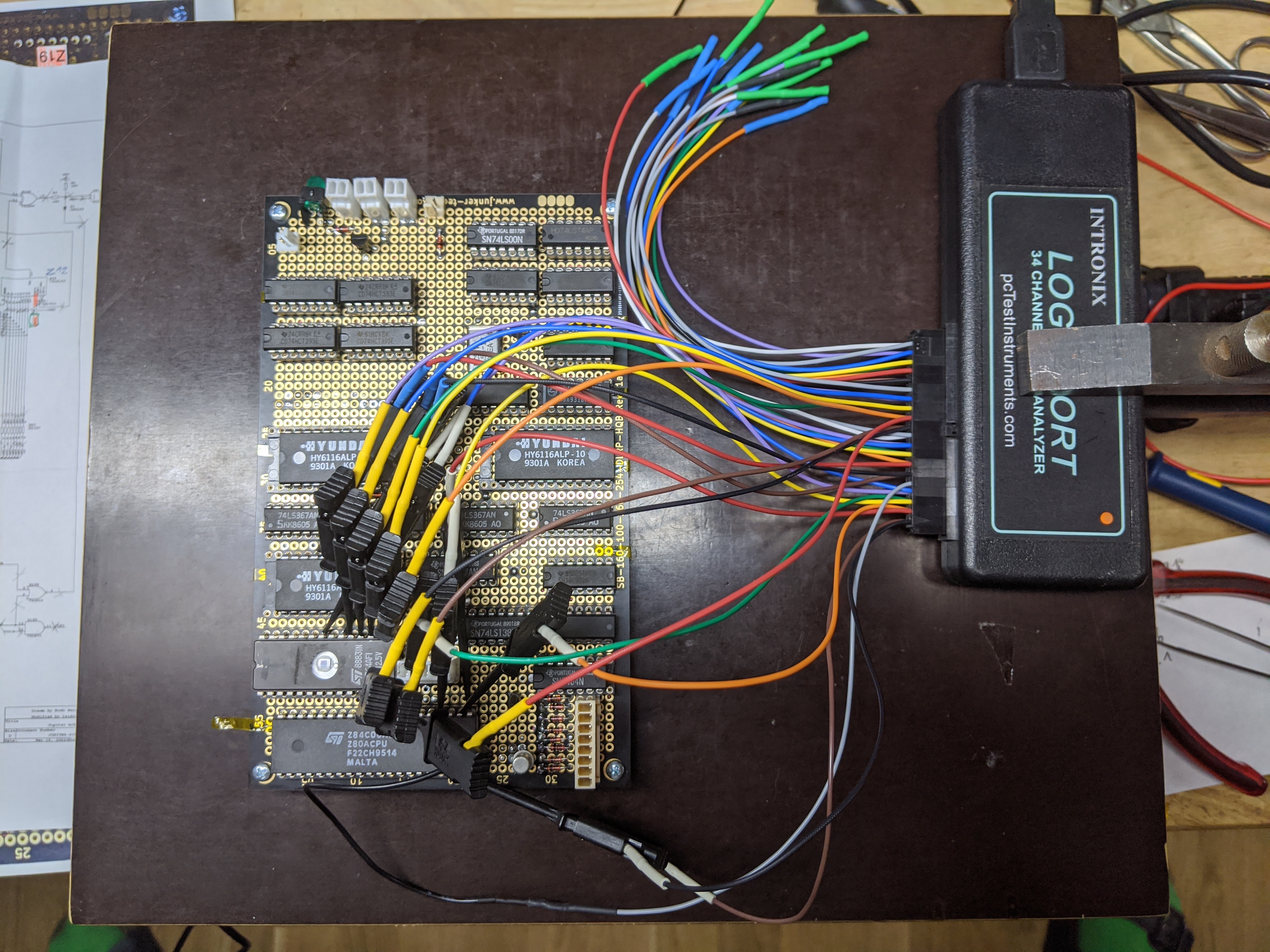
In order to figure out what’s going on with the CPU, I concentrated on these signals:
- MREQ and IOREQ indicate access to memory and I/O, respectively
- RD and WR are active (low) during read and write accesses
- M1 is machine cycle 1, active during instruction fetch reads
- ROMCS and RAMCS are the ROM and RAM chip select
- DATA is the data bus (D7-D0)
Here’s the waveform that can be observed when the machine is running:

As M1 is active during instruction fetch, it is possible to determine
the instructions that the CPU is executing by looking at the data bus
at the end of each M1 cycle. In the trace above, the instructions
fetched and executed are CBh 6Eh (BIT 5, (HL)) and 28h FCh (JR Z, -2). I checked the ROM
listing to see where
this instruction sequence is present, and found it right here:

So, it seems that the CPU ran through the whole initialization code and is waiting for the user’s input.
Next up
At this point, it seems that the CPU is actually running and the video generation hardware also works. It is my suspicion that the video output signal does not have the appropriate levels and/or impedance so I’ll try to address the issue in the analog realm. Once I have output, I’m going to connect a keyboard and see if the character generation works.
Any comments or advice on how to move forward would be greatly appreciated at this point. I’ve also pondered whether I should be describing how the Jupiter Ace actually works while I find out in the process. If you’re interested in reading more, please encourage me by leaving a comment here or on Twitter
